Mar 14
Rob
The following is the Task Group Warrior standard operating procedures for Carrier operations; These operations replace the Prestart, Taxi, Take Off, RV, Landing sections of the TGW fixed wing land S.O.P’s. If an item is not referenced in this document it maintains the same Standard Operating Procedure as those for Land based aircraft.
List of Abbreviations/Acronyms
| ACL – Automatic Carrier Landing ADF – Automatic Direction finder AEW – Airborne Early Warning AFCS – Automatic Flight Control System AG – Arresting Gear ALRE – Aircraft Launching and Recovery Equipment. APC – Approach Power Compensator ATC – Air traffic Control BRC – Base Recovery Course CAG – Commander, Air Group CAP – Combat Air Patrol CATCC – Carrier air traffic Control center CCA. – Carrier Controlled Approach. CH. – Channel CO – Commanding Officer COMM. – Communications COMSEC – Communications Security CV. – Aircraft Carrier CV/N – Conventional/Nuclear Aircraft Carrier CVW – Carrier Air Wing DLM. – Datalink Monitor DME – Distance Measuring Equipment DR – Dead Reckoning DRR – Departure reference radial EAT. – Expected approach time. EEAT – Emergency Expected Approach Time. FAF – Final Approach Fix FB – Final Bearing FL – Flight Level GCI – Ground Controlled Intercept GPS – Global Positioning System HF – High Frequency HUD – Heads Up Display IAF – Initial approach fix | ICLS – Instrument Carrier Landing System IFF – Identification Friend or foe IFLOLS – Improved Fresnel Lens Optical Landing System IFR – Instrument Flight Rules IMC – Instrument Meteorological Conditions ITL – Intent To Launch JBD – Jet Blast Deflector KIAS – Knots Indicated Airspeed LSO – Landing Signal Officer MCC – Monitor Control Console MDA – Minimum Descent Altitude MSL – Mean Sea Level nm – Nautical Miles NOTAM – Notice To Airman OLS – Optical Landing System OOD – Officer of the Deck OPORD – Operation Order PALS – Precision approach and landing system PLAT – Pilot Landing and Approach Television REL – Relative RF – Radio Frequency RV – Rendezvous SAR – Search and Rescue SOP – Standard Operating Procedure TACAN – TACtical Air Navigation UHF – Ultra High Frequency VFR – Visual Flight Rules VHF – Very High Frequency VMC – Visual Meteorological conditions WOD – Wind Over Deck ZIPLIP – No radio transmissions. |
1.0 The Carrier
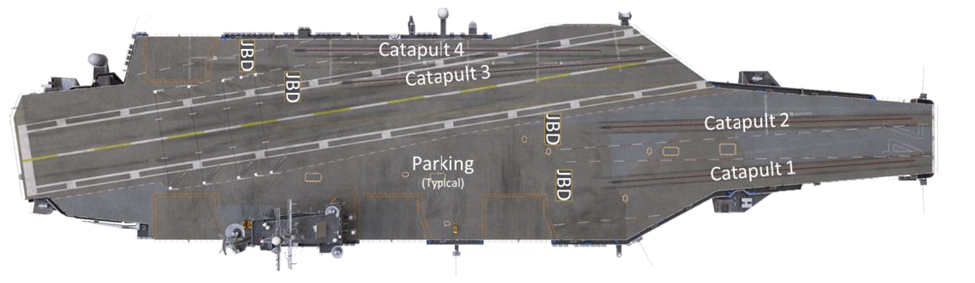
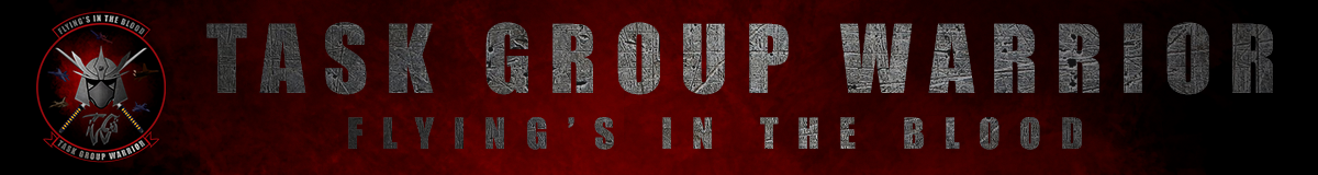
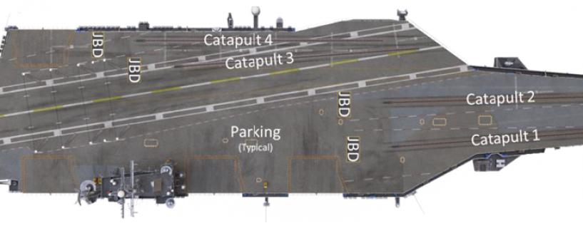
Fig 1.0 Carrier Parking and Catapults
TGW uses the Super Carrier as our standard Aircraft Carrier in all missions and will always refer to the boat as ‘Mother’, Home Plate or the carrier’s nickname (eg Rough Rider), Pilots should be aware of the following information for their carrier.
- The carrier’s ATC frequency. For TGW this will generally be defaulted to 118.30 if no other ATC frequency is on this channel and only 1 carrier is in use.
- The Carriers TACAN, for TGW typically this is 53 or 71X
- The Carriers ILS Frequency, for TGW typically this is Channel 1 or 7
- The Carriers Link 4 Data Link frequency. Typically this is 331.0
- If Player LSO is on they will be on 118.350
- If Player Marshall is on they will be on 301.00 UHF
The Carrier itself can operate in 4 forms of operations and up to 3 ‘Cases’ these are as follows
- Closed Ops – In this state the Deck is closed to all operations and the carrier is not accepting recovery or launch operations. This is done typically if for some reason the carrier is damaged and unable to safely operate.
- Launch Operations – In this state the Carrier is conducting Launch operations only, no recovery operations will take place unless an emergency is declared, All 4 catapults are in operation at this time.
- Recovery Operations – In this state no Launch operations take place and the carrier is solely focused on the recovery of aircraft. It is typically turned into the wind to allow for the least amount of cross wind across the deck, items like the ILS and Link 4 Datalink are active and the Deck area is kept as clear as possible.
- CAT-TRAP-CAT (Launch and Recovery Operations) in this state of operations both Launch and Recovery are going on at the same time, typically staged so that as one aircraft has just finished trapping, one or two aircraft are launching from the boat. During these operations CAT 1 and 2 are operational while CAT 3 and 4 are not.
As mentioned, CASE may also be applied to these operations of which there are 3 levels of CASE directly impacted by the current weather and visibility conditions.
- CASE I operations take place when cloud cover is at least 3,000ft above the carrier and visibility is at or greater than 5 nautical miles, it is only used however during the day.
- CASE II operations is a hybrid of CASE I and CASE III and is used when IMC conditions may be encountered between 1,000 and 3,000ft and visibility is still at or greater than 5 nautical miles. Typically it is used only during the day.
- CASE III operations take place any time that conditions do not allow for CASE I or II operations, this includes any time IMC conditions may be a major factor and at night.
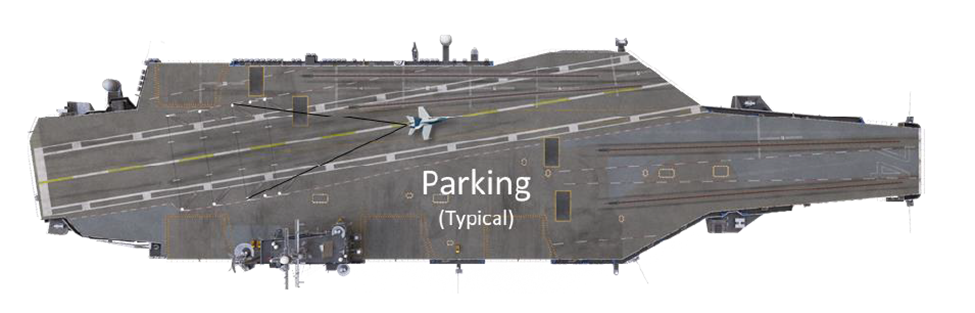
Fig 1.2 Landing Operations
2.0 Take Off Operations
2.1 Prestart.
Upon loading into your aircraft, you should proceed as mission brief requires for start up but the standard steps are as follows:
1. Check immediate surrounds for any issues.
2. Load your aircraft with ord if not already pre-loaded Using alt+’.
2.2 Start
Once the aircraft is loaded with ordnance and fuel, you may proceed with the start, starting operations are to be conducted as follows.
1. Bring up any systems required to use your radios.
2. Connect to the published Radio Frequency for the Carrier that you are starting on.
3. Once Connected inform the carrier that you are in the process of starting your aircraft as follows:
- Non-Zip-lip: “Mother, <callsign> starting this time.” Example: “Mother, Crimson 1-1 starting this time”.
- Zip-Lip: The engagement of your anti-collision light.
4. Proceed with start up as per your standard checks.
2.3 Taxi
Prior to taxi, all pilots on a carrier should take time to double check any conflicts that may need to be addressed for movement to an assigned catapult, they should also be aware that if recovery and launch operations are happening at the same time of any aircraft currently in the landing pattern. At no point in time will any aircraft taxiing for a catapult cross the landing area if an aircraft is:
- About to enter the ‘groove’
- In the grove
On commencement of taxing units should make mother and any other pilot aware by:
a. Non-Zip Lip: Calling on mothers frequency: “Mother, <callsign> taxing Cat #” example: “Mother, Crimson 1-1 taxing Cat 1 “
b. Zip Lip: Engagement of your Navigation lights, while maintaining low enough speed to avoid collisions.
When taxiing to the Catapults the pattern to follow is that Cat 1 and 2 should be used first, then Cat 3 & 4 so long as Landing operations are not under way at the same time.
2.4 Hook Up
During hook up, pilots should follow ground crew commands. If using the F-14 Tomcat understand that Cat 3 and 4 will be limited to a single Cat.
2.5 Take Off
Once pilots are on their assigned Catapults, take off consists of two parts, the ‘Run Up’, and the ‘Shot’, the shot itself is automatic and players should consult the method for dealing with the shot for their individual aircraft; however most are ‘Hands off until positive rate’.
The Run-up itself should be carried out as per your aircraft operational manual, following the instructions of the Catapult Crew, normally this consists of in the F/A-18 making certain that you are correctly in trim for your weight with your flaps in T.O and your engines are in Afterburner. In the F-14A you will wish to trim at least 3 – 5 degree’s nose up, flaps to half and run engines up to burner. In the F-14B you will follow the steps for the F-14A however you will keep both engines at MIL power.
Prior to launch, pilots should inform those in the Carrier Area of Operations that they are preparing to launch; this can be done in one of two ways depending on if Zip Lip Comms are in effect or not.
- Non-Zip Lip: Calling on mothers frequency: “Mother Callsign, Shooting Cat #”
- Zip-Lip: Flashing your Navigational Lights slowly 2 times.
Be aware that some aircraft flashing your lights may cause the in-game Carrier to consider that you are ready for launch, as such you should be ready for the cat stroke to happen as you flash your lights.
Again, the shot itself should be carried out as per the manual for your actual aircraft.
A clearing turn should be made once safely in the air, see fig xx below.
2.6 Departure
Once the ‘shot’ is complete pilots should transition to departure operations, departure operations are in effect until you are beyond 10NM DME from the Carrier during which time you are required to do the following depending on the ‘CASE’ of operations currently in effect
2.6.1 CASE I
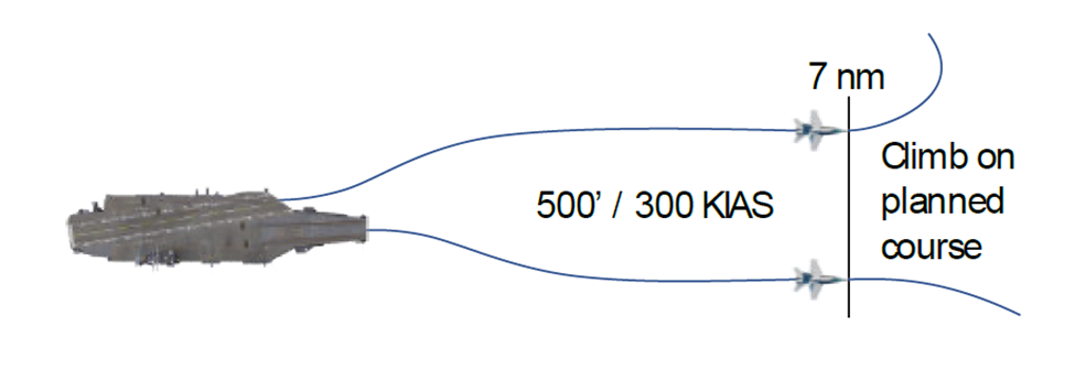
Fig 2.1 (CASE I Departure)
This departure type may be utilized when it is anticipated that flights will not encounter instrument conditions during departures and rendezvous with weather conditions no lower than 3,000ft and Visibility 5 nm or greater.
After a clearing turn, proceed straight ahead paralleling the Base Recovery Course (BRC) at 500ft until 7nm. After which you are clear for unrestricted climb in VFR conditions.
2.6.1.1 CASE I Rendezvous
Rendezvous shall conform to the briefing given prior to flight, else units should aim to RV either
- Overhead the aircraft carrier at an altitude of no less than 7,000ft MSL.
- Enroute while maintaining 350ft.
2.6.2 CASE II Departure
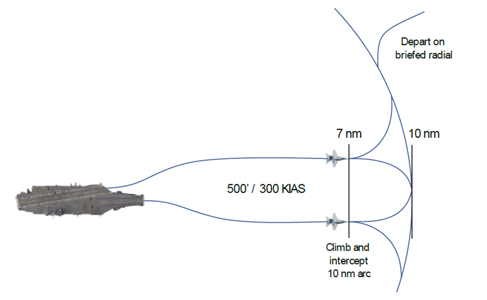
Fig 2.2 CASE II Departure
This departure type may be utilized when visual conditions at the ship exist down to a ceiling of 1,000ft and visibility of 5 nm or greater; all launch operations shall be on Mother Departure Control frequency. (typically all mother comms are on the same frequency.)
After the clearing turn , proceed straight ahead at 500ft parallel to the BRC. At 7nm turn to intercept the 10-nm arc, maintaining VFR conditions. Jets should maintain 300 KIAS until VMC on top of the weather.
2.6.3 CASE III Departure
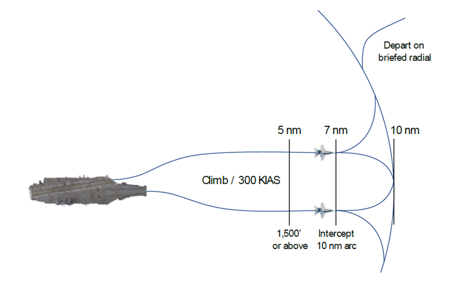
FIG 2.3 CASE III Departure
This departure shall be used whenever weather conditions on the ship are below the CASE II departure minimums and during all night operations unless modified by the CAG or CO of the boat in question. CASE III departures automatically require CASE III recoveries. The launch shall be on Mothers departure control frequency, a minimum launch interval of 30 seconds shall be used between aircraft.
When CAT-TRAP-CAT operations are in effect (Launching and Recovery at the same time) Planes must be launched in a manner that does not conflict separation with possible bolter/waveoff aircraft.
On launch Climb straight ahead accelerating to 300 KIAS to cross 5nm at or above 1,500ftMSL. At 7nm, execute a turn to fly the 10-nm arc until intercepting the departure radial.
2.6.3.1 CASE II/III Rendezvous
CASE II/III aircraft shall rendezvous between 20 – 50 NM from the carrier on the left side of the departure radial at a pre-briefed altitude (example, 2,000ft above the Cloud layer or 20,000ft). this does not preclude any visual RV procedures as directed by the mission commander.
2.6.4 IMC at Altitude
If weather conditions are currently IMC, the first aircraft of each flight shall report on the departure frequency on passing FL 180 if not on top. Unless operational necessity dictates otherwise, aircraft should follow ATC instructions (if available) to be stacked at IMC appropriate altitudes or assign themselves IMC altitudes based on the first Aircraft’s intended level off altitude until RV. An example of this with four aircraft expected to be on the same departure radial of 330, altitude assignments would be as follows:
- First Aircraft FL 240
- Second Aircraft FL230
- Third Aircraft FL220
- Fourth Aircraft FL210
Note: All Carrier based aircraft will use MSL Altitudes when below 18,000ft MSL and Flight Level altitudes at and above 18,000ft MSL
3.0 Recovery Operations
Recovery operations covers any operation where the pilot is considering landing, recovery operations start when an aircraft enters the CCA and broadcasts their intent to land, from this moment on unless hostile aircraft or ground forces cause issues you are expected to be following the Recovery Operations SOP described here.
3.1 Carrier Control Area (CCA)
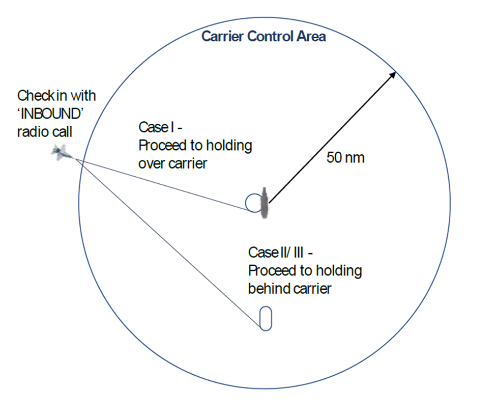
Fig 3.1 – The CCA
Pilots enter the Carrier Control Area (CCA) upon entering 50 nm of the Carriers DME, at this point they are expected to contact mother using the AI communications and/or human communications. On contact, pilots are expected to use the following communication method.
On your own: MARSHALL, <SIDE NUMBER>, Marking Mom’s [bearing from mother to player] for [range], angels [altitude], state [fuel state]
With more then 1 person in your Flight: MARSHALL, <SIDE NUMBER>, Holding hands with <SIDE NUMBER>, Marking mom’s <Bearing from mother to player> for <range>, angels <Altitude>, <number in flight>, Low State <Lowest members fuel state>
Example: “Marshall, 221, Holding hands with 244, Marking mums 244 for 49, angels 24, 2, Low state 4.3”
The Carrier Marshal will respond as per the Super Carrier Doc if AI. If a player is in control they will adjust and change things depending on the current CASE the correct CASE items are below.
3.1.1 CASE I INBOUND TO MARSHAL CALLS
Marshal Call: <SIDE NUMBER>, Mothers weather is <Visibility>, <clouds>, Altimeter is <pressure>, CASE I recovery expected BRC is <Heading of Carrier> Report see me at 10.
Pilots Will respond with: “<SIDE NUMBER>
Example:
Marshal: 221, Mothers weather is Visibility greater then 10, Clouds 16,000 scattered, Altimeter is 29.97, CASE One recovery expected BRC is 300, Report see me at 10.
Pilot: 221.
3.1.2 CASE II/III INBOUND TO MARSHAL CALLS
Marshal Call: <Side Number>, <Ship Callsign> Marshal, CASE II/III Recovery, CV-1 approach, expected BRC <Carrier Heading> Altimeter <pressure>. <Side Number>, Marshal mother’s <Marshal Radial Bearing> radial, <distance> DME, angels <Altitude> Expected approach time is <time>
That side number will respond with a read back of: <Side Number>, Marshal on the <radial bearing> for <range> DME, angels <altitude> expected approach time <time>, Approach button is <Channel>
Marshal will respond with either corrections of ‘Read back Correct’
If pilots are ‘holding hands’ Marshal will at this point read the next pilot’s details.
3.1.3 10nm Zone.
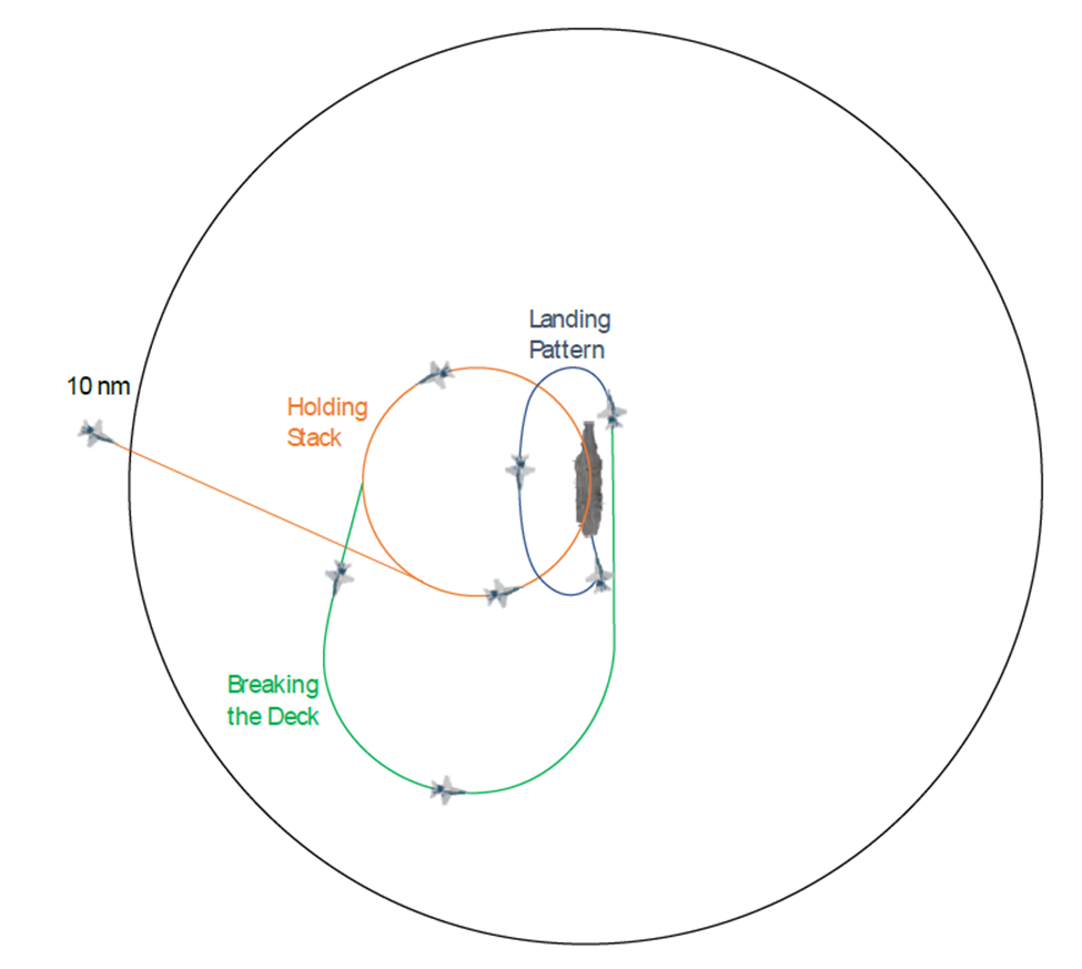
Fig 3.2 The 10 nautical mile zone.
At any point that an Aircraft enters within 10 nm of the Carrier, there are certain limitations that pilots must observe if under CCA control. Under CASE I operations, pilots are expected to be at the standard Marshal altitudes (2-5,000ft) by this ‘bubble’ and at 250 knots for the ‘hold’, the only time they are to leave marshal altitude is for the actual recovery or to use the recovery tanker. Comms MUST be monitored and the carrier must be told that you ‘SEE YOU AT 10’.
Under CASE II/III recovery, Pilots must be at their assigned marshal altitude if crossing the 10nm bubble to their holding pattern and must otherwise only violate this bubble during the landing or bolter stage of their recovery.
3.2 CASE I Recovery
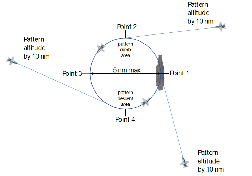
Figure 3.3 CASE I Marshall Stack & Spin Pattern
CASE I recoveries are conducted if Cloud layer is above 3,000ft and visibility is at or greater than 5nm, The flight leader retains full responsibility for proper navigation and separation from other aircraft. All returning flights will check in with Marshal control when entering the carrier control area or as soon as they are released by another controlling agency. Aircraft should normally be switched to Tower Control at 10nm (See you at 10)
3.2.1 Jet/Turboprop Aircraft Port Holding/Spin Pattern
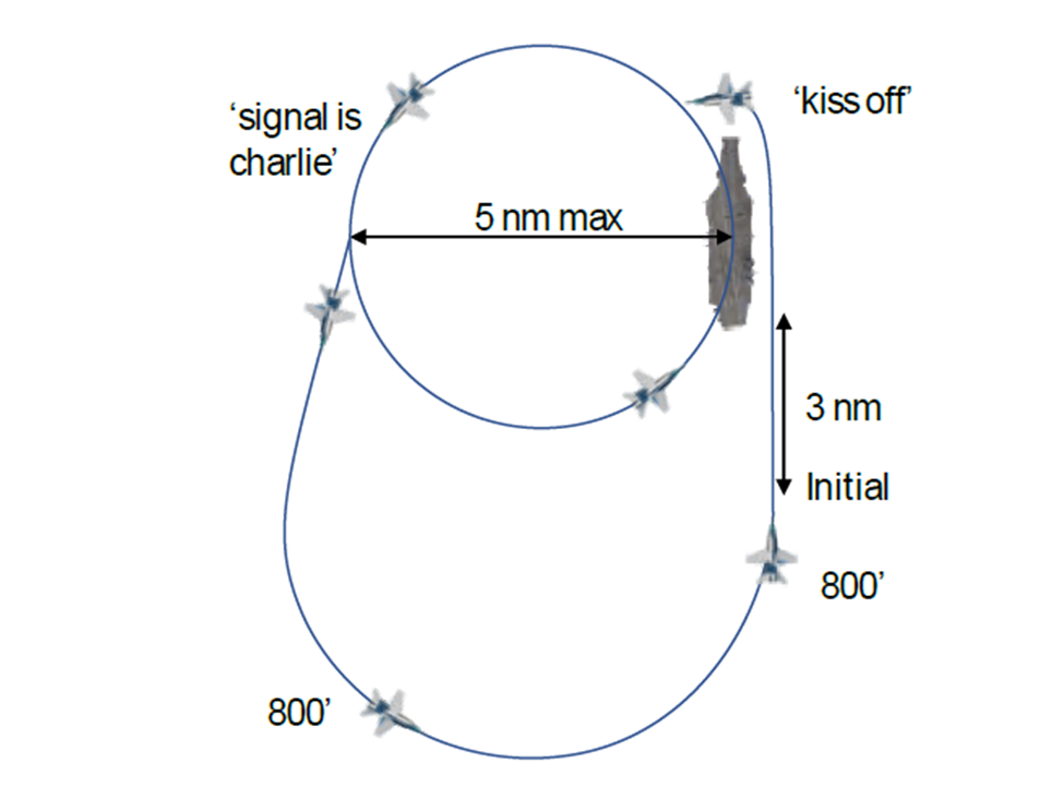
Fig 3.4 Port Holding Pattern
The Jet and turboprop port holding pattern is a left-hand pattern tangent with the BRC or expected BRC with the Carrier anchored at the 3-o’clock position and a maximum diameter of 5 nm. Flights should be established at their assigned port holding altitude 10nm prior to entering the pattern and Entry into the pattern should be tangible (at either point 1,2,3,4) with wings level. Minimum altitudes assigned will be 2,000ft and 1,000ft separation will be maintained between flights as required.
Within the pattern, aircraft will maintain prescribed separation distances and landing order in the port pattern, climbs will only be done within the Point 1-3 region (Upper 3,9) and descents shall occur only in the 3 – 1 region (Lower 3,9).
Departure from the port holding pattern for break entry shall be accomplished aft of the ship’s beam. Decent to the break from the pattern is commenced by the lowest aircraft of flight in time to meet ramp time or when given a ‘Signal Charlie’ call. This descent should be planned to arrive at the initial point (3 nm astern, 800ft) wings level. Paralleling the BRC.
Flight leaders shall exercise caution to avoid aircraft in the tanker pattern at all times.
Flight leader shall also execute either a normal break or spin for all or a portion of his flight. The spin pattern shall be flown at 1,200ft within 3nm of the ship. A maximum of six aircraft shall be in the landing pattern at any given time. No aircraft shall break more than 4 nm ahead of the ship. Pilots must exercise caution to avoid departing aircraft and other aircraft in the starboard holding pattern. If a Denial of landing (Delta) is given after commencing descent from the port holding pattern, but prior to entering the landing pattern, aircraft shall climb or descend as required and enter the spin pattern (1,200ft) unless specifically directed otherwise. Aircraft in the landing pattern shall continue to maintain proper interval, fly the landing pattern at 600ft until otherwise directed. Flights directed to ‘spin’ or ‘reenter hold’ shall climb only on the upwind or crosswind leg ahead of the ship’s beam. Aircraft reentering the break from the spin pattern have priority over aircraft entering the pattern from the port holding pattern.
3.2.2 Landing Pattern Entry
The landing pattern depicted in figure x-x is used by fixed wing aircraft during day VFR (CASE I/II) operations. The purpose of day CASE I/II operations is to allow for a primarily pilot controlled pattern and reduce the total recovery time compared to those of CASE III operations.
After reaching initial pilots will commence entry into the break, checking that the carrier deck is in a state for recovery as they pass the ship and that no aircraft is on CAT 3 or 4, All breaks shall be made at 800ft and All breaks shall be Level, No aircraft will break further then 4nm ahead of the carrier and no more than 4 aircraft are permitted to make the break at any one time.
A descent to 600ft to intercept the downwind leg of the landing pattern shall commence when established downwind and must be completed before reaching the 180 position.
3.2.3 Downwind Leg and Approach Turn.
The landing pattern downwind leg is flown at 600ft AGL, 1 to 1 ½ NM abeam of the ship. Aircraft in the VFR landing pattern should be established in the intended landing configuration, wings level at 600 ft with landing checklist completed by reaching 180. At the 180, pilots should begin the approach turn and a gradual descent to pass the 90-degree position at 450-500ft AGL. The pilot should then continue the approach turn until they intercept the extended centerline of the carrier angeled deck and acquire the optical landing system. The approach turn from the 180 to the start of the Grove should take aprox 45 seconds.
3.2.4 Groove and Touchdown
Pilots should have the aircraft rolling wings level on centerline with a centered ball as they come out of the approach turn to allow for 15 – 20 seconds groove time before the aircraft touchdown on deck. Upon visual sighting of the Optical Landing system and LSO request of Pilot sight of the ball at the ¾ smile mark with ““¾ Mile call the ball”” Pilots will respond with:
“<side number>, <aircraft type>, Ball <Fuel State>”
Example: 244, Hornet, Ball, 3.2
Pilots will continue to fly the BALL and LSO commands (see 3.7 for LSO commands) as given until touchdown at which time pilots will apply power as appropriate (in the F/A-18 this is Afterburner, in the F-14A/B this is MIL POWER), and prepare to bolter. If the aircraft successfully arrests then pilots will reduce power to idle to clear the hook from the cable and then move to taxi for parking as quickly as possible.
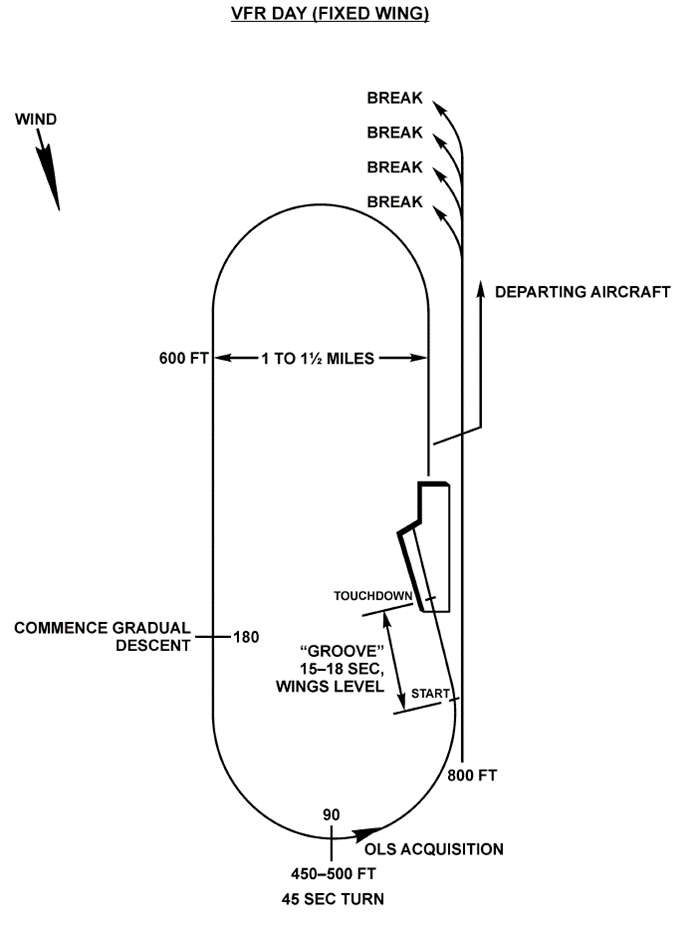
Figure 3.5 Landing Pattern
3.2.5 Waveoff/Bolters and Touch and Go
DCS Does not handle wave off and bolters properly however all pilots should be prepared for a wave off into the pattern at any time during landing approach up until touch down. Any aircraft approaching in an unsafe condition or situation (eg.. Too low, unstable, insufficient interval, etc) will be waved off rather than allowed to continue to touch down. Upon direction to wave off, pilots WILL add power as necessary to stop the aircrafts rate of descent and commence a climb.
In the case of a Touch and Go or Bolter the pilot shall turn to parallel the BRC. Corrections to do so should not be attempted until a definite climb has been established. Pilots shall climb to 600ft, then turn to join the downwind leg of the landing pattern making certain to maintain normal intervals, upon rejoining the pattern they should operate as per normal traffic.
3.2.6 Landing Pattern Departure
Aircraft departing CASE I/II landing pattern shall remain in the pattern until established on the upwind leg. From the upwind leg, aircraft shall clear the pattern by executing a 20° turn to starboard followed by a 20° reversal to parallel the BRC until clear of the landing pattern.
3.2.7 DRAG (Straight in Approach)
If pilots are requesting a straight in approach, it shall be initiated at a sufficient distance astern to:
- Be established positively on the glidepath and approach airspeed at a minimum of 1 ½ nm from the boat.
- Remain aware of any other aircraft currently in tha pattern.
3.3 CASE II Recovery
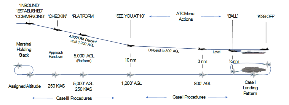
Figure 3.6 Case II recovery
This approach shall be utilized when weather conditions are such that a flight may encounter instrument conditions during the descent but visual conditions of at least 1,000ft cloud ceiling and 5nm visibility exist at the ship. Positive control shall be utilized until the pilot is inside 10nm and reports the ship in sight. During CASE II recoveries it should be expected that a shift to CASE III may be required due to weather deterioration.
The maximum number of aircraft allowed in the landing pattern is Six during CASE II operations.
CASE II recoveries will NOT be conducted concurrently with CASE III recoveries. SHould any doubt exist regarding the ability to maintain VMC over the Carrier CASE III shall be utilized.
CASE II operations conduct CASE III procedures until reaching the 10 NM mark at which point they return to CASE I procedures.
3.4 CASE III Recovery
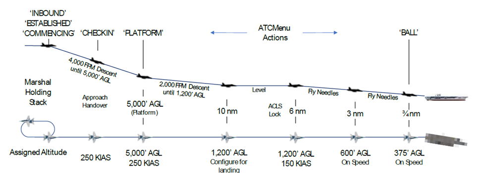
Figure 3.7 Case III recovery
This approach shall be utilized whenever existing weather at the ship is below CASE II minimums and during all flight operations conducted during true night periods on DCS. Case III Recoveries shall be made with single aircraft. Section approaches will be approved only when an emergency situation exists. Formation penetrations/approaches by disimilar aircraft shall not be attempted except in extreme circumstances where no safer options are available.
CASE III recoveries may be conducted concurrently with CASE I and II launches.
At night during VMC conditions, helicopters may be cleared to the starboard holding pattern. If so, restrictions on helicopters will be as day VMC.
3.4.1 Marshal Procedure
Pilots will inform Marshal of establishment at their assigned marshal by broadcasting: <side number> Established.
3.4.1.1 Jet/Turboprop Aircraft
Aircraft shall be directed to marshal on a TACAN Fix of 180 radial relative to the expected final bearing at a distance of 1nm for every 1,000ft plus 15nm, (angels + 15). The holding pattern is a left hand, 6 minute racetrack pattern. The inbound leg shall pass over the holding fix. In no case will aircraft be assigned a base altitude of less than 6,000ft.
3.4.1.2 Helicopter
T.B.D.
3.4.1.3 Overhead Marshal
Overhead marshals may be utilized as geographical or operational circumstances necessitate. The assigned inbound magnetic heading to the holding fix should coincide with the outound magnetic radial of the approach.
3.4.1.4 En Route Radar Approaches
In the event an aircraft or flight cannot reach the marshal point in time to make an assigned approach time, an en route radar approach may be used to place the flight in the proper approach sequence.
If such is underway, the Marshal/approach controller shall employ positive radar control and provide pilots with guidance to get into position for penetration below the cloud deck.
3.4.2 Marshal Instructions
Marshal Shall give all aircraft the following information prior to the aircraft entering Marshal:
- Case Recovery
- Type of Approach
- Expected Final Bearing
- Altimeter
- Marshal holding instructions
- Expected approach time
- Expected approach button
- Time Check
- Vector to marsh (if required)
- Multiple marshal stack information. (Radials/Altitudes)
To reduce traffic any items of general or collective interest may be transmitted by marshal or approach control as a “99” broadcast
Pilots should respond with read backs when given specific marshal instructions. Example of CASE II marshal instructions are given above during the inbound sequence.
3.4.3 Departing Marshal
Each pilot shall adjust his holding pattern to depart marshal at the assigned EAT. Early or late departure shall be reported to marshal control immediately so that adjustments may be accomplished if required.
Pilots will broadcast to Marshal on departure with <Side Number>, Commencing.
3.4.4 Initial Separation
Unless weather or operational conditions dictate otherwise, aircraft departing marshal will be nominally separated by 1 minute.
3.4.5 Frequency Changes
Any changes to radio frequencies, IFF, DL mode/code that may require accomplishment by the pilot should be conducted no later than entering platform altitude except under emergency conditions. The aircraft shall be in straight and level flight should any changes be required once below an altitude of 2,500ft.
3.4.6 Instrument Approach Procedures
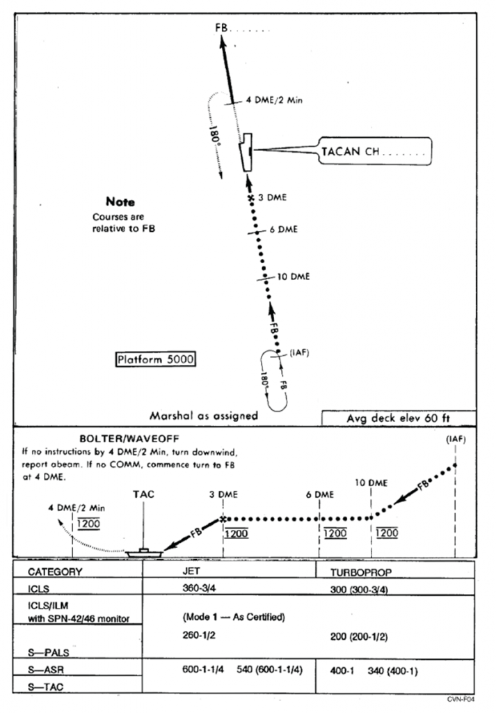
Figure 3.8 IAP Procedure plate
The approaches described in this paragraph are designed primarily for single-carrier operations; however can be modified to be used for both multi-carrier operations and for recoveries during EMCON conditions.
The approach charts (fig xx to xx) are designed for use with all aircraft carriers regardless of weather conditions. All ships use standard approaches so that pilots may transition from one ship to another or from visual to instrument conditions with minimum changes to operating procedure.
3.4.6.1 Approach Minimums
TGW operates under an approach minimums when using I.A.P’s and all pilots are expected to respect the minimums, if no alternate recovery airfield is available and continual failure to have visual on the landing area occurs then pilots may continue for final landing.
Approach Type Minimum Safe Altitude
ICLS 360 @ ¾ NM.
ICLS/ILM/S-PALS MODE I – As certified or 260 @ ½ nm
MODE II – 200 @ ½ nm
MODE III- 200 @ ½ nm
S-ASR/S-TAC 600 1 ¼ Nm.
3.4.6.2 Penetration/Approach
All aircraft shall descend at 250 KIAS and 4,000ft Per minute until platform is reached, at which point descent shall be shallowed to 2,000ft per minute. Unless otherwise directed, Aircraft shall commence transition to landing configuration at the 8-nm Fix.
Upon reaching Platform altitude pilots should transmit <SIDE NUMBER>, Platform.
3.4.6.3 Correcting to the final Bearing.
- Jet aircraft on the CV-1 approach will correct from the marshal radial to the final bearing at 20 nm in the following manner:
- The pilot shall make a gradual correction when the final bearing is within 10° of the reciprocal of the marshal radial.
- The pilot shall turn 30° when the final bearing is greater than 10° from the reciprocal of the marshal radial If not established on the final bearing at 12nm, the pilot shall fly the 12nm arc until intercepting the final bearing.
- Jet aircraft on the CV-2 approach will correct to the final bearing in the following manner:
- If the final bearing decreases, fly 90° of penetration turn and arc to the new final bearing.
- If final bearing increases, fly the standard penetration turn continuing to intercept the new final bearing prior to the 10nm DME fix.
3.4.7.4 PALS Mode I Approach.
Aircraft conducting PALS Mode I approaches with ceiling and visibility less than 200 feet or ½ mile must be able to operate with the ACLS systems visible and active at all times. For those conducting a PALS Mode I CCA approach to a ACLS equipped ship the following procedures shall be followed.
- Jet aircraft shall pass through the 6nm DME fix at 1,200ft MSL, 150 KIAS and in the landing configuration, at this point they will commence slowing to final approach speed. The pilot should engage aircraft Autopilot and Autothrottle systems in the correct modes. Normally between 4 to 6nm the pilot will receive a mode 4 datalink check signal to verify that the ship has ACLS data link connection
- The final controller will acquire the aircraft between 3.5 and 8nm and the PALS ready/lock-on indicator will be displayed. At that time the controller will report ACLS lock-on, the controller will report lock-on with range, verify needles, and issue instructions as needed for the aircraft to intercept the centerline, as well as instructing the pilot to report ‘coupled’
This is reported in DCS as Final Radar Contact - At lock-on the pilot will verify that the PAL display agree with needles and verify that the system is fully coupled, for example: 221 Lock-on 5 miles, Say needles” The pilot shall report needle position, for example: 221, Needles up and on”. The reporter responds “Concur report coupled.”
Note: This audio is done automatically with DCS’s ATC. You just need to verify that you’re situation and instruments are correct. - The final controller shall report mode, the aircraft should be flown in coupled mode for at least 30 seconds before intercepting the glidepath.
- The final controller shall advise the pilot at minimums the pilot shall respond with “ball” report and include the words coupled. For example, “201, Hornet, Ball, Three point zero, coupled. Expect ILM needle deviation inside ¼ nm from touchdown. Use the ball inside Minimums.
3.4.7.5 PALS Mode IA Approach
Mode IA approaches are conducted the same as Mode I except that the pilot shall uncouple at or prior to reaching approach minimums and report “uncoupled” if the pilot uncouples at the “ball” call, they shall include the word “uncoupling” in the ball report. For example, “201, uncoupling, hornet, ball, three point two, auto” When the pilot reports uncoupling, the controller shall downgrade the PALS to Mode II.
3.4.7.6 PALS Mode II/IID Approach
- Mode II approaches are conducted the same as Modes I/IA until the point of ACLS lock-on, at that time the controller shall report lock-on with range, verify needle presentation and issue instructions as required example: “221 Lock-on, 5 Miles, Say needles.” The pilot shall respond with their needle position for example: 221, Needles Up and Left” the controller shall concur or downgrade the approach to ICLS or Mode III, “201 concur, Fly Mode II” or “201, disregard needles, fly bullseye”
- When the controller enables the FD mode, the symbol is displayed on the Aircraft HUD, the pilot should follow the ACLS commands.
3.4.7.7 PALS Mode III Approach
Mode three is not implemented in DCS at this time.
3.4.7.8 ICLS Approach
Jet aircraft shall pass through the 6nm DME fix at 1,200ft, 150 KIAS in the landing configuration and commence slowing to final approach speed. ILM information shall be used to intercept and fly the glideslope and centerline, and TACAN information shall be used for DME information until reaching ICLS minimum. ILM information may be used to achieve lineup early in the approach.
3.4.7.9 Non Precision Approach
Non-precision approaches are not modeled by DCS’s ATC at this time, pilots are able to conduct the operations under TACAN instruments, however they will not receive guidance from ATC typically to maintain correct azimuth and altitude. In the case of Jet Aircraft in DCS for TGW use you may descend to 600ft after passing the 3nm DME fix, you may not reduce altitude below this until you are established with visual aids or fuel critical.
3.4.8 Missed Approach/Waveoff/Bolter.
Jet Aircraft shall climb straight ahead on the extended final bearing to 1,200ft altitude and await instructions from approach control (if players LSO is on). If no Human LSO is on players may follow the No-Contact directions below to re-enter the pattern as DCS does not support currently rejoining the pattern after a bolter/wave-off.
All waveoff/bolter pattern turns shall be level.
If no instructions are received prior to reaching 4nm or 2 minutes ahead of the ship, the pilot will attempt to make contact with the ship, giving identification and position. If instructions are not received, he will assume communication failure and execute a turn downwind abeam, if communication is not reestablished he will proceed downwind and re-enter as follows:
- Commence turn to final at the 4nm DME or 2 minutes past abeam position.
- PALS aircraft should be alert for Data-Link displays.
3.4.9 Delta Procedures.
Delta procedures can only occur when under human control, DCS ATC does not support Delta Procedures.
In the event that the deck becomes fouled or an excessive number of aircraft bolter or wave-off, the CCA officer shall issue via marshal control a signal Delta. The Delta signal shall be accompanied by the number of minutes of delay in even increments but never less than four, required to resume recovery operations. Ie. Delta 4, Delta 6 etc.
Aircraft will react as follows:
- In Marshal – Aircraft shall continue holding and await assignment of new EAT, if none is given adjust EAT by the Delta Time.
- Commenced Aircraft – Commenced aircraft above 7,000ft shall level off at the next lower odd altitude and hold on the inbound bearing at a range in nm equal to holding altitude in thousands of feet plus base distance (angels + 15). The holding pattern shall be the same as the original marshal pattern. Aircrews shall report established in holding with new altitude and await assignment of new EAT, aircraft below 7,000ft will continue the approach.
- Marshal control shall issue new EAT’s as soon as possible. To preclude two aircraft having the same EAT, new EATs shall be issued from the latest to the earliest (Top of the stack to the bottom), Pilots shall acknowledge new EATS.
- Lost communications – In the case of lost communications with Marshall aircraft in the marshall stack shall commence approach at the last acknowledged EAT. Aircraft between marshal and 7,000ftthat have established Delta holding and subsequently realized lost communications prior to acknowledging a new EAT shall commence approach immediately.
Pilots shall take a 30°cut to the right to intercept a track 10° to the right of the inbound bearing and continue inbound to the ship.
WARNING: Be alert for possible aircraft in Delta Holding at lower altitudes.
3.4.10 Voice Communication Procedures.
3.4.10.1 Compulsory Arrival, Marshal and Approach Voice Reports
- Entrance into carrier control area – Information required from flight lead.(see 3.1)
- Receipt of:
- Marshal instructions
- Type recovery
- EAT or Charlie time
- Altimeter settings
- Entering holding/marshal with altitude, fuel state, and any hung/unexpected ord.
- Altitude changes
- Commencing approach, with fuel state, altimeter setting
- Frequency changes
- Platform
- Ten Miles
- Coupled/needles as appropriate and command control if mode I/IA approach.
- Breaking away (Section approaches only)
- Ball call report – (Side number, aircraft type, ball or Clara, fuel state, hung/unexpected ord, coupled/uncoupled (if applicable), auto/manual)
- Waving off
- Abeam, with fuel state after bolter/waveoff.
3.4.10.2 Phraseology
Standard ATC and precision instrument approach phraseology shall be used with the following exceptions:
- Fuel state reports (thousands of points for example “2.9”)
- Altitude (angels, for example, “1.4”)
- Heading changes on CASE III final approaches after lock-on or final radar changes (normally soft heading, for example 221, right five)
3.5 Recovering Aircraft
3.5.1 Preparation for Recovery
DCS does not easily allow us to change deck configurations on the fly, as such most preparations for recovery by the carrier items are pointless,when operating however under cyclic ops and were able a recovery helicopter should be launched if not already airborne as should a recovery tanker. If possible these events should occur 15 minutes prior to the start of the recovery window.
Upon receiving notice that a recovery window is to open, no aircraft may use the waist catapults, (Cats 3 and 4) 5 minutes prior to the window opening.
The LSO shall perform the following items:
- Conduct a two-way radio check on appropriate circuits.
- Ensure that the LSO platform is functional and ready for landing operations.
3.5.2 Flight Deck Procedures
At the current time DCS does not allow users to control the flight deck, as such TGW runs the following flight deck limitations during recovery operations:
- No aircraft shall enter the landing area unless permission is given by the LSO or Controlling officer.
- No aircraft shall attempt to use Catapults 3 or 4 during recovery operations.
- The deck shall be considered foul under any of the following conditions:
- Any aircraft is within the no cross boundaries of the runway.
- Any wreckage is within the no cross boundaries of the runway.
- The cut lights or wave off light is lit.
- After each touch and go, arrestment, bolter or waveoff.
- All taxi signals shall be answered promptly and accurately unless a pilot considers that a dangerous situation exists or is developing, in which case he shall stop immediately.
- If a pilot loses sight of his director (when/if DCS adds directors) he shall stop immediately.
3.5.3 Control of the Landing Pattern (VMC)
This information is for player controlled ATC/LSO only, using DCS these are fixed and can not be changed.
The air officer is charged with the overall control of the VMC landing pattern (figure 3.2.3) and is assisted by the LSO specific responsibilities are as follows.
3.5.3.1 Air Officer (Air Boss)
- Provide pilot with sufficient information to ensure that aircraft are established in the landing pattern in time to meet the expected Charlie time.
- Assign or revise the landing order as necessary.
- Regulate the number of aircraft in the landing pattern to ensure a steady flow of traffic while preventing the pattern from becoming extended or overcrowded.
- Monitor the landing interval.
- Whenever possible maintain visual contact with all aircraft in the Charlie pattern.
- Maintain an accurate count of the aircraft the be recovered and inform ship controller when only 2 remain (if ship is under player control).
- Monitor the upwind pattern, being particularly alert to warn pilots of aircraft boltering or waving off of their proximity to aircraft launching or breaking.
- Maintain visual contact with any aircraft that have radio failure.
- Inform the LSO of any unusual conditions affecting the normal recovery of aircraft.
3.5.3.2 LSO (Under the supervision of the Air Officer)
- Control of all fixed wing aircraft approaches after the 180° position
- Ensure the approaching aircraft are properly configured.
- Monitor the operation of the OLS and check the approach radar/ICLS glidepath angel
- Instruct and supervise the talker if not the active LSO.
- Assist in controlling aircraft that have radio failure by flashing the cut or waveofflights in accordance with the signals delimited in figure xx.
- Wherever possible, maintain visual contact with all aircraft in the Charlie pattern.
- In form the air officer of any unusual conditions affecting the safe recovery of aircraft.
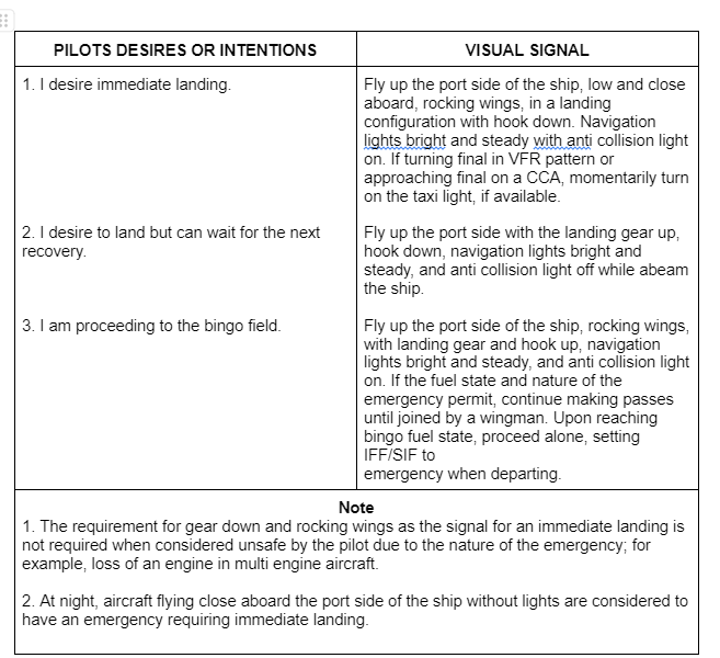
Figure 3.9
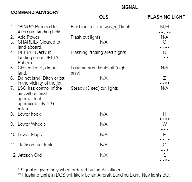
Figure 3.10
3.5.4 Landing of Aircraft
As stated in the various approaches upon the ¾ nm mark pilots are under control of the LSO, upon landing all pilots are expected to go to MIL or AB power for no less than 5 seconds and no longer than 15 to assist in the case of a Bolter. Once Successful trap is confirmed pilots should:
- Immediately carry out required steps to clear their tailhook.
- As quickly as possible move their aircraft to clear the landing area.
3.5.5 Aircraft Lights
Upon landing aircraft should quickly turn off any navigational lights and/or landing and taxi lighting. If the aircraft has suffered nosewheel steering loss or other issues that may preclude taxing from the landing area aircraft are to:
- Immediately turn all navigational lights to maximum brightness.
- Immediately turn on their main landing lights and/or taxi lights.
Upon clearing the landing area main landing lights and/or taxi lights should be turned off.
3.6 Parking
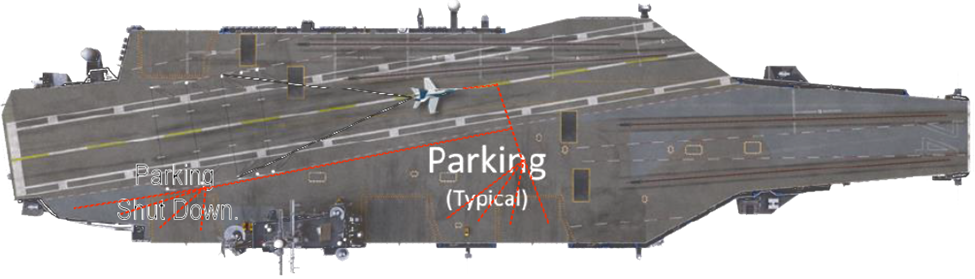
Figure 3.11 Parking areas by type.
Parking on the carrier in DCS is difficult at the current time due to lack of Marshalling and other systems. For our SOP we have the following procedures when parking your aircraft based on what you are doing. If DCS adds deck crew marshaling then you will follow the marshaller as per above, in absence of this use the following procedures depending on what you are doing.
3.6.1 Regenerating (Rearm/Refueling)
If rearming and refueling pilots should move to park along the typical parking area behind Cat 1 and Cat 2’s blast deflectors, while keeping away from the elevator closest to the Island (due to it being a spawn location) and allowing for enough room if possible for catapult operations to continue.
3.6.2 Shutting Down
If shutting down your airframe you should start by parking towards the rear of the boat outside of the landing zone, then if these positions are occupied moving to park in the locations used in the Regenerating zones.
3.7 LSO Communications
During the final 3/4 of a nautical mile aircraft are under the control of the LSO who will give verbal directions to the pilot to aide in correcting any deviations that maybe occuring which will impact the touch down. Pilots are expected to follow these verbal commands unless doing so puts their jet into danger and LSO’s when active are expected to give instructions that are clear, safe and understandable.
3.7.1 LSO Commands
The following is a list of commands that the LSO may give to pilots, tone and inflection matter if something is given empathis either through firm, multiple or shouted word pilots should respond rapidly.
| Callout | By | Meaning |
|---|---|---|
| Paddles Contact | LSO | You are abeam the LSO platform, in contact with LSO begin final turn |
| 3/4 mile call the ball | LSO | Can you see the Bullseye/Meatball if so respond. |
| side,type, Ball, fuel 118, Hornet, Ball 3.0 | Pilot | Modex, Aircraft Type, If you have the ball, Fuel State, if Coupled, If Auto Throttle is engaged. |
| Roger Ball | LSO | Aircraft is cleared to continue |
| Your High | LSO | You are above glide slope, work it down |
| Power | LSO | Add Power aircraft is below glide slope |
| Don’t Settle | LSO | Do not let the planes rate of descent change |
| Right for lineup | LSO | Come right to center line, your lined up to far left |
| Come Left | LSO | Come left to centerline, your lined up to far right |
| Your lined up <direction> | LSO | You need to correct for this your to far left/right of center. |
| Easy with it | LSO | Less control corrections, your over correcting |
| Burner! | LSO | Select Afterburner now! |
| Wave-Off! | LSO | Execute Wave-Off/Go around procedures immediately. |
| Bolter | LSO | You missed the wires. |
3.7.2 LSO Grading
After you have made a landing attempt you will be given an evaluation, either by a human LSO or by DCS’s own LSO, these grades are posted on the Greenie Board and the last 10 help make up your on-going rolling score. The grades and comments that can be given during this process are listed below.
3.7.2.1 Grading Remarks
| Grade | Score | Rating | Score |
|---|---|---|---|
| _OK_ | OK underline | Perfect pass/Unicorn. Rarely given | 5 |
| OK | OK Pass | Pass with very minimal deviations | 4 |
| (OK) | Fair pass | Pass with one or more safe deviations | 3 |
| B | Bolter | Safe pass were aircraft failed to catch any wires. | 2.5 |
| — | No Grade | Pass with gross but still safe deviations, failure to listen to instruction, inappropriate actions (eg fail to call the ball) | 2 |
| TWO | Technique Waveoff | Pass was unsafe and required aborting. | 1 |
| C | Cut Pass | Unsafe pass with unacceptable deviations | 0 |
| WO | Foul Deck Waveoff | Aborted pass after landing deck fouled or blocked, no points, not counted towards average. | NG |
Apart from the overall grading comments will be given for your actual trap this is known as a score sheet with the developments of each landing noted in Symbology. You can find out far more about this in the NATOPS LSO Manual However we have the most used items here. The Grading is done based on sectors as shown in the image below.
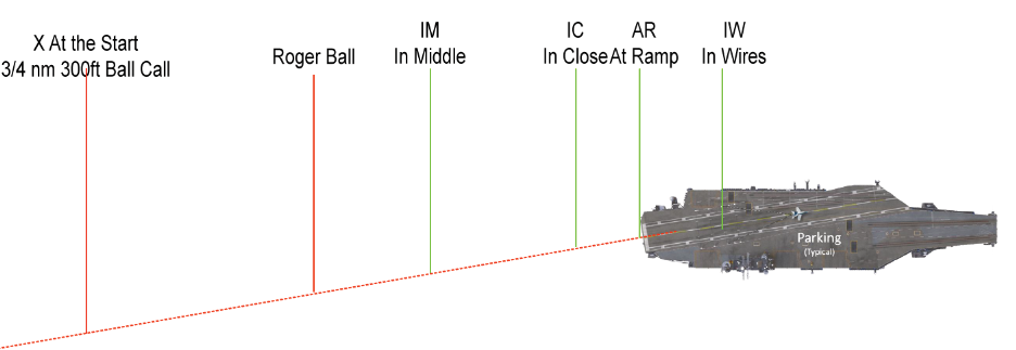
Figure 3.12 Grading Zones
3.7.2.2 LSO Grading Symbology
The following is a list of grading symbology that can be used to mark a trap an example is given after.
| Symbology | Meaning | Symbology | Meaning |
|---|---|---|---|
| WO | Waveoff | () | A little |
| WOP | Waveoff Pattern | _comment_ | A lot |
| OWO | Own waveoff | [] | Ignored LSO |
| TWO | Technique Waveoff | O | Signal acknowledged too slowly |
| TLU | Test Lineup | OC | Over Corrected |
| NC | No Count | • | Indicates On |
| – | Indicates to | PATT | Pattern |
| (A) | Auto | BC | Missed/Incorrect Ballcall |
| AFU | All Fouled up/All fucked up | AA | Angling Approach |
| ACC | Accelerate | B | Flat Glideslope |
| C | Climbing | CB | Coming Back to Line up |
| CD | Coming Down | CH | Chased |
| CO | Come-On | DD | Deck Down |
| DEC | Decelerate | DL | Drifted Left |
| DN | Dropped Nose | DR | Drifted Right |
| DU | Deck Up | EG | Eased Gun/s |
| F | Fast | FD | Fouled Deck |
| GLI | Gliding Approach | H | High |
| HO | Hold Off | LIG | Long in Groove |
| LL | Landed Left | LLU | Late LineUp |
| LO | Low | ||
| LR | Landed Right | LTR | Left To Right |
| LU | LineUp | LUL | Lined Up Left |
| LUR | Lined Up Right | LWD | Left Wing Down (DWL) |
| N | Nose | NC | Nice Correction |
| ND | Nose Down | NEA | Not Enough Attitude |
| NEP | Not Enough Power | NERD | Not Enough Rate of Descent |
| NERR | Not enough right Rudder | NESA | Not Enough Straight Away |
| NH | No Hook | NSU | Not Set Up |
| OR | OverRotate | OS | Overshoot |
| OSCB | Overshot Coming Back | P | Power |
| PD | Pitching Deck | PNU | Pulled Nose Up |
| ROT | Rotate | RUD | Rudder |
| RUF | Rough | RWD | Right Wing Down (DWR) |
| RR | Right Rudder | RTL | Right To Left |
| S | Settle | SD | Spotted Deck |
| SHT | Ship’s Turn | SKD | Skid |
| SLO | Slow | SRD | Stopped Rate of Descent |
| ST | Steep Turn | TCA | Too Close Abeam |
| TMA | Too Much Altitude | TMP | Too Much Power |
| TMRD | Too Much Rate of Descent | TMRR | Too Much Right Rudder |
| TTL | Turned Too Late | TTS | Turned Too Soon |
| TWA | Too Wide Abeam | W | Wings |
| WU | Wrapped Up | XCTL | Cross Control |
| / | Fly through glideslope (Up) | \ | Fly through glideslope (down) |
| LLWD | Landed Left Wing Down | LRWD | Landed Right Wing Down |
| LNF | Landed Nose First | ^ | Over the Top |
3.7.2.3 Example Gradings
Hornet – Swampy (OK) 3.0 C1, W2, AA LULX (FH)LULIM SLO(H)LULIC LULAR
In the above grade we can see that Swampy flying a F/A-18C Hornet made an OK 3 Point pass (OK) with a Case 1 recovery, catching the 2nd Wire.
During the trap he was:
AA LULX
Angeling Approach (AA) and Lined Up Left (LUL) at the Start (X)
(FH)LULIM
A little Fast and High ( (FH) ) and Lined Up Left (LUL) in the middle (IM)
SLO(H)LULIC
Slow (SLO) and a little High (H) as well as Lined Up Left (LUL) in close (IC)
LULAR
and Lined Up Left (LUL) at the ramp (AR).
An example of a bolter is given here:
Hornet – Swampy — 2.5, C1 -, _AA_(LO)_LUL_X LUL DRIM LURIC LURAR
In the above grade we can see that Swampy flying a F/A-18C hornet bolted and failed to catch a wire making a 2.5 point pass while doing a case 1 recovery.
During the Trap he was:
_AA_(LO)_LUL_X
Angel Approaching by a Lot (_AA_) Slightly Low ( (LO) ) Lined Up Left alot (_LUL_) at the Start (X)
LUL DRIM
Lined Up Left (LUL) Drifted Right (DR) in middle (IM)
LURIC
Lined Up Right (LUR) In Close (IC)
LURAR
Lined up Right (LUR) at Ramp (AR)
4.0 RECOVERY TANKER
4.1.1 CASE I/II
After launching all tankers will begin their stack overhead mother at an altitude no less than 1,500ft and typically no higher than 8,000ft, TGW typically runs its S-3B recovery tanker at an altitude of 6,000ft doing 250-300 KIAS. The recovery tanker may be in either a circular orbit overhead the carrier or a 10 – 25 nm racetrack orbit along the carrier BRC.
4.1.2 CASE III
After launching all tankers will begin their stack overhead mother at an altitude no less than 1,000ft above the overcast layer or VMC between layers and no less than 2,500ft at any time. TGW Typically runs its S-3B recovery tanker at 6,000ft unless conditions preclude this.
4.2 Minimum Fuel levels
Aircraft who reach the following limits should expect to tank before taking on any further recoveries.
- For F-14A/B model aircraft their fuel state has reached less than 2,000 pounds.
- For FA/-18 aircraft their fuel state has reached 1,500 or less pounds.
In either case aircraft are expected to take on 2,000 pounds of fuel from the recovery tanker, the need to move to the recovery tanker should be announced to any controlling agencies and if no controlling agency is on broadcast on the carrier frequency as follows:
side, trick or treating for <amount> will report when done.
example:
501, trick or treating for 2.0 will report complete.
When completed aircraft should report with new fuel state:
Example:
501, trick or treat complete new state 4.3
4.3 Rendezvous Procedures
4.3.1 RV Low (Day and Night VMC)
Upon need to use the recovery tanker any aircraft should push to the tankers frequency and use the DCS comms to request refueling at which point, They should rejoin the tanker at 500 below the recovery tankers altitude, if the tanker is currently refueling they should join into right echelon formation stacked for quick flow onto the drogue, if the tanker is free they may move immediately into precontact position.
Upon completion of refueling, aircraft should depart by left hand turn dropping no more than 250 ft until clear of the tanker and re-establish in the marshall stack or approach as required/directed.
4.3.2 RV High (IMC)
RV High tanker recovery should be carried out using standard TGW Tanking procedures.


